
Services Browse all products ›
 Mining & Oil & Gas Services 7 active subcategories Building & Construction & Maintenance Services 2 active subcategories Industrial Production & Manufacturing Services 9 active subcategories Industrial Cleaning Services 4 active subcategories Environmental Services 4 active subcategories Transportation & Storage & Mail Services 6 active subcategories Management & Business Professionals & Administrative Services 7 active subcategories Engineering & Research & Technology Based Services 7 active subcategories Editorial & Design & Graphic & Fine Art Services 6 active subcategories Public Utilities & Public Sector Related Services 3 active subcategories Financial & Insurance Services 5 active subcategories Healthcare Services 7 active subcategories Education & Training Services 5 active subcategories Travel & Food & Lodging & Entertainment Services 6 active subcategories Personal & Domestic Services 2 active subcategories National Defense & Public Order & Security & Safety Services 1 active subcategories Politics & Civic Affairs Services 4 active subcategories Organizations & Clubs 3 active subcategories
 Gifts, Sports & Toys Browse all products ›

Machinery, Industrial Parts & Tools Browse all products ›
 Mining & Well Drilling Machinery & Accessories 5 active subcategories Farming & Fishing & Forestry & Wildlife Machinery & Accessories 2 active subcategories Building & Construction Machinery & Accessories 1 active subcategories Industrial Manufacturing & Processing Machinery & Accessories 19 active subcategories Material Handling & Conditioning & Storage Machinery & their Accessories & Supplies 5 active subcategories Power Generation & Distribution Machinery & Accessories 5 active subcategories Tools & General Machinery 4 active subcategories Structures & Building & Construction & Manufacturing Components & Supplies 14 active subcategories Manufacturing Components & Supplies 29 active subcategories Distribution & Conditioning Systems & Equipment & Components 4 active subcategories Laboratory & Measuring & Observing & Testing Equipment 3 active subcategories Cleaning Equipment & Supplies 4 active subcategories Service Industry Machinery & Equipment & Supplies 2 active subcategories
 Transportation Browse all products ›

Mineral, Textile, Herbal and Animal Products Browse all products ›

Agriculture & Food Browse all products ›

Health & Beauty Browse all products ›

Oil, Gas, Chemical, Rubber and Plastics Browse all products ›

Electric, Electronics and Telecommunications Browse all products ›
 Electronic Components & Supplies 6 active subcategories Electrical systems & Lighting & components & accessories & supplies 4 active subcategories Information Technology Broadcasting & Telecommunications 5 active subcategories Defense & Law Enforcement & Security & Safety Equipment & Supplies 5 active subcategories
 Apparel,Textiles & Accessories Browse all products ›

Packaging, Advertising & Office Browse all products ›


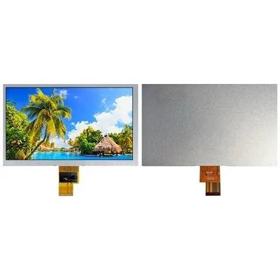
7 Inch TFT Color LCD Display 40 Pins 280 Nits 1024x600 With Lvds Interface

7 Inch 1024x600 Tft Display With Lvds Interface 40 Pins 280 Nits Brightness General Description: This 7 inch tft lcd display of WY700TN40-24 has a display resolution of 1024 (RGB) x 600 (WVGA), an aspect ratio of 16:9 (W:H), and a vertical RGB bar arrangement of pixels. Its viewing size is 1...
7 Inch 1024x600 Tft Display With Lvds Interface 40 Pins 280 Nits Brightness
General Description:
This 7 inch tft lcd display of WY700TN40-24 has a display resolution of 1024 (RGB) x 600 (WVGA), an aspect ratio of 16:9 (W:H), and a vertical RGB bar arrangement of pixels. Its viewing size is 153.61×90(W×H) mm, appearance size is 164×103(W×H)×3.5(thick) mm.
Specifications:
Item
Contents
Unit
LCD
LCD Type TFT / Transmissive / Normally Black
--
Viewing direction 6 O'clock --
Backlight White LED x 24 --
Interface LVDS interface --
Outline Dimension (lcm) 164.0W) ×103.0(H) × 3.5 (T) mm
Glass area (W×H×T) 161.4 × 99.6 × 1.0 mm
Active area (W×H) 153.61 ×90.0 mm
Number of Dots 1024(RGB) ×600 --
Dot pitch (W×H) 0.05 × 0.15 mm
Pixel pitch (W×H) 0.15 × 0.15 mm
Operating Temperature -10 ~ +50 ℃
Storage temperature -20 ~ +60 ℃
Polarizer
Top: 45度film
--
Bottom: 45度film
Absolute Maximum Ratings:
Item Symbol Rating Unit
Digital Supply Voltage VDD -0.3 to +3.96 V
Operating Temperature range TOP -10 to +50 ℃
Storage Temperature range TST -20 to +60 ℃
Electrical Specifications:
Item Symbol Min. Type. Max. Unit
Digital Power Supply Voltage VDD 3.0 3.3 3.6 V
Analog Supply Voltage AVDD 8.4 9.6 10.0 V
Gate On Voltage VGH 17 18 19 V
Gate Off Voltage VGL -9 -8 -7 V
Common Voltage VCOM 2.4 3.0 3.6 V
Backlight Electrical Specifications:
Item Symbol Condition Min Typ Max Unit
Forward Voltage VF IF=160mA - 9.6 - V
Uniformity △Bp - 80 - - %
LCM Luminance Lv IF=16mA 280 - cd/m2
Interface Connection:
PIN No.
SYMBOL
Function
1 VCOM Common voltage
2-3 VDD Digital power
3 VDD Digital power
5
RESET
Global reset pin. Active low to enter reset state. Suggest to connecting with an RC reset circuit for stability.Normally pull high. (R=10KΩ, C=0.1μF)
6
STBYB
Standby mode, normally pull high
STBYB=”1”, normal operation
STBYB=”0”,timing control, source driver will turn off, all output are high-Z
7 GND Ground
8 RXIN0- Negative LVDS differential data inputs
9 RXIN0+ Positive LVDS differential data inputs
10 GND Ground
11 RXIN1- Negative LVDS differential data inputs
12 RXIN1+ Positive LVDS differential data inputs
13 GND Ground
14 RXIN2- Negative LVDS differential data inputs
15 RXIN2+ Positive LVDS differential data inputs
16 GND Ground
17 RXCLKIN- Negative LVDS differential clock inputs
18 RXCLKIN+ Positive LVDS differential clock inputs
19 GND Ground
20 RXIN3- Negative LVDS differential data inputs
21 RXIN3+ Positive LVDS differential data inputs
22 GND Ground
23-24 NC NC
25 GND Ground
26 NC NC
27 DIMO Backlight CABC controller signal output
28 SELB
6bit/8bit mode select
H : 6bit / L : 8bit
29 AVDD Power for Analog Circuit
30 GND Ground
31-32 LED K LED Cathode
33 L/R Horizontal inversion
34 U/D Vertical inversion
35 VGL Negative power for TFT
36-37 GND Ground
38 VGH Positive power for TFT
39-40 LED A LED Anode
Handling Precautions:
1.Do not leave the module operation or storage in Strong light . Strong light exposure causes degradation of polarizer and color filter.
2.The polarizer surface should not come in contact with any other object. It is recommended that they be stored in the container in which they were shipped.


